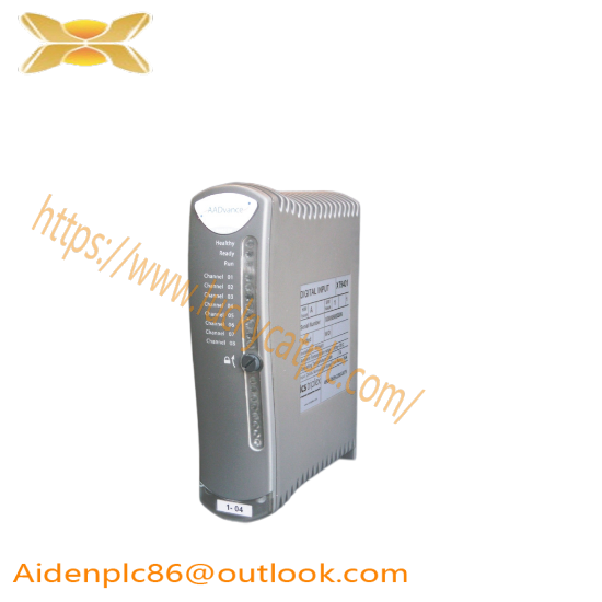
Install a T9110 Processor Module
• Before inserting a new processor module, examine it for damage.
• The identification labels on the sides of the module will be hidden after the module is installed. Therefore before installation make a record of the location of the module and the details shown on the label.
. If you are installing more than one processor module make sure they all have the same firmware build.
Installation
1. Examine the coding pegs on the T9100 processor base unit and make sure they complement the sockets on the rear of the processor module:
2. Place the processor module on to the coding pegs. Make sure the slot on the head of the module locking screw is vertical and then push the module home until the connectors are fully mated.
3. Using a broad (9mm) flat blade screwdriver turn the module locking screw clockwise to lock.
Replace a Faulty Processor Back-up Battery
Use the following official Rockwell Automation battery or one of an equivalent specification.
Part No and Description
T9905: Polycarbon monofluoride Lithium Coin Battery, BR2032 (recommended type), 20 mm dia; Nominal voltage 3 V; Nominal capacity (mAh.) 190; Continuous standard load (mA.) 0.03; Operating temperature -30 °C to +80°C, supplied by Panasonic.
The battery has a design life of 10 years when the processor module is continually powered; for processor modules that are un-powered, the design life is up to 6 months.
Procedure
To replace a faulty battery, do the following:
1. Use a small cross head screwdriver to release and remove the battery cover
2. Remove the battery by pulling on the blue ribbon.
3. Insert a new battery, orientate it the positive (+) terminal to the right. Trap the ribbon behind the new battery so it can be removed in the future and then push the battery into the holder.
4. Put the cover back and secure it with the cross head screw.
5. Push the Fault Reset button on the processor module. The processor Healthy LED will go green (applies if the module is part of a running system).
If the battery is replaced when more than one processor module is installed then the processor clock will be updated automatically through synchronization.
If you have previously set up SNTP when you set up your processor module then the clock will be reset to the current time automatically. If you have not set up SNTP it is recommended that you do so, as this will not only reset the processor clock but will also keep the time accurately during operation. Refer to the applicable software publication for SNTP set up instructions:
• AADvance Controller Configuration Guide Workbench 1.x, publication ICSTT-RM405
• AADvance Controller Configuration Guide Workbench 2.x, publication ICSTT-RM458
• AADvance®-Trusted® SIS Workstation software User Guide, publication ICSTT-UM002
The following applies:
• If the battery is replaced when only one processor module is installed and the processor module is not powered up and SNTP has not been set up, you must set the clock to the current time as soon as practicable.
• The battery does not do any function while the processor module is powered and the application is running. The Processor’s Real Time Clock provides Date and Time data for SOE functions and also forthe Processor diagnostic log entries.
The specific functions that the battery maintains on complete loss of power are the following:
• Real Time Clock – The battery provides power to the RTC chip itself.
• Retained Variables – Data forretained variables is stored at the end of each application scan in a portion of RAM, backed by the battery. On restoration of power, the retained data is loaded back into the variables assigned as retained variables for use by the application scan.
• Diagnostic logs – The processors diagnostic logs are stored in the portion of RAM backed by the battery.
Set the Real Time Clock Manually
If the system has only one controller and does not have a different time server, you have to set the processorreal-time clock manually using RTC variables. The following procedure assists in setting the clock:
Set up the following variables in the Dictionary
RTC Control Rack Variables (all BOOLEAN Outputs)
• RTC Control: RTC_Read
• RTC Control: RTC_Write
• RTC Control: Year
• RTC Control: Month
• RTC Control: Day of Month
• RTC Control: Hours
• RTC Control: Minutes
• RTC Control: Seconds
• RTC Control: Milliseconds
RTC Status Variables (All Word Inputs)
• RTC Status: Year
• RTC Status: Month
• RTC Status: Day of Month
• RTC Status: Hours
• RTC Status: Minutes
• RTC Status: Seconds
• RTC Status: Milliseconds
RTC Program Rack Variables
• RTC Program: Year
• RTC Program: Month
• RTC Program: Day of Month
• RTC Program: Hours
• RTC Program: Minutes
• RTC Program: Seconds
• RTC Program: Milliseconds
Procedure to Check the Current Date and Time
1. Wire the processor variables. Refer to the topic “Wire Processor Variables”.
2. Build and download the program or perform an on-line update.
3. Check the current date and time settings:
• Enter Debug mode
• Request IXL Restricted Access
• Force the RTC Read Boolean and all the time fields in the RTC Control Rack Variables to TRUE
• The RTC Status Variables will show the current date and time in the processor
Related product recommendations:
Rockwell Automation 44BEZ-R1MPB1-A2
Allen-Bradley 595-B02
Rockwell A-B 1492-PG6IEC
HP 70820A
Schneider D2E146-AP47-C3
BENTLY NEVADA CP-0408803-01
Rexroth MAC071C-0-US-4-C/095-B-0/WI517LV
ABB PFEA112-20 3BSE050091R20
Honeywell 51198947-100B
Siemens 225A9643P001
Honeywell 3311S2
Kollmorgen B-102-A-32-B3
Schneider 490NRP95400
A-B MPAR-A1300B-V2BMP
ABB DI803 3BSE022362R1
More…


